Wood has been used as a building material for thousands of years, being second only to stone in terms of its rich and storied history in the world of construction. One of the biggest advantages of using wood as a building material is that it is a natural resource, making it readily available and economically feasible. It is remarkably strong in relation to its weight, provides good insulation from the cold, is highly machinable, and can be fabricated into all kinds of shapes and sizes to fit practically any construction need.
Biggest disadvantage of using wood is that being a natural resource you can not get a good quality control over the material. This drives the factor of safeties in design to be higher than man made/manufactured materials such as steel. The best example is our lab test sample which popped way below the capacity of timber. (Also think about this, in the design of steel structures we use a low factor of safety, about 1.15. What would be the factor of safety for design with timber?)
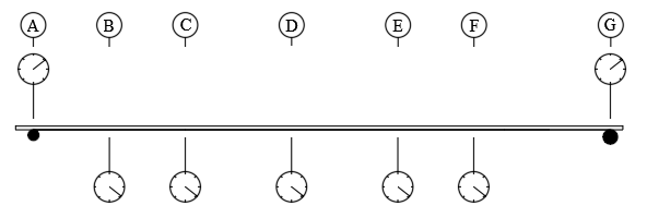
What did we do?
We loaded the timber beam in the crown position under two loading conditions. The deflection in the beam was recorded from the seven dial gages. The final failure load was recorded when the beam popped!
What do I want in the report?
Sample Calculations
1. Theoretical deflections for the two loading cases at the mid span
For load of 2000 lbs,
i. First loading case:
\begin{equation} \delta_{theo} = \delta_A ( 1 - \frac{x}{L_1}) + \delta_G (\frac{x}{L_1}) + \frac{P (3 L^2_1 x - 4 x^3)}{48 E I} \end{equation}
ii. Second loading case:
\begin{equation} \delta _{theo}= \delta_B ( 1 - \frac{x}{L_2}) + \delta_F (\frac{x}{L_2}) + \frac{P a x (L_2 - x)}{4 E I} \end{equation}
2. Young’s Modulus calculation for two loading cases
For load of 2000 lbs, calculate the Young’s modulus using the experimental mid span deflection:
i. First loading case:
\begin{equation} E_{case 1} = \frac{P (3 L^2_1 x - 4 x^3)}{48 I (\delta_e - \delta_A ( 1 - \frac{x}{L_1}) - \delta_G (\frac{x}{L_1}))} \end{equation}
ii. Second loading case:
\begin{equation} E_{case 2} = \frac{P a x (L_2 - x)}{4 I (\delta_e - \delta_B ( 1 - \frac{x}{L_2}) - \delta_F (\frac{x}{L_2}))} \end{equation}
3. Bending stress at failure
Using 4000lb as th failure load, use $M y / I$ to calculate bending stress at failure.
- Please convert the units to SI
- Just use the mid span deflection for sample calculation.
- The different parameters are:
- $\delta_{e}$ = experimental deflection
- $\delta_{theo}$ = theoretical deflection
- $\delta_{A}$ = deflection in dial A
- $\delta_{B}$ = deflection in dial B
- $\delta_{C}$ = deflection in dial C
- $\delta_{G}$ = deflection in dial G
- P = load applied
- I = moment of inertia (width x depth^3) / 12)
- a = distance between support and load (A and B in load case 2)
- $L_1$ = whole length of the beam
- $L_2$ = length between loads (B and F)
- x = distance to mid span ($L_1$/2 for case 1 and $L_2$/2 for case 2)
- $\delta_{e}$ = experimental deflection
Attachments
Tables:
- Young’s modulus from both cases along with % difference
- Theoretical displacement and % difference for:
- Point B,C and D for first load case
- Point C and D for second load case
Graphs/Plots
- 1 plot for theoretical and experimental deflections vs distance from support A for Load case 1 for all the loads.